I have an idea
Work out the shape, purpose and next design questions.
ProtoChat / Before the CAD conversation
An idea, a sketch, an existing part or unfinished CAD is enough to start. Tell us what it needs to do and where you need design help.
You don’t need to choose a material, process or tolerance before we talk.
← Manufacturing resourcesStart where you are
Choose the closest starting point. You can change direction as the project becomes clearer.
Work out the shape, purpose and next design questions.

Turn what you have into a clearer model or design brief.
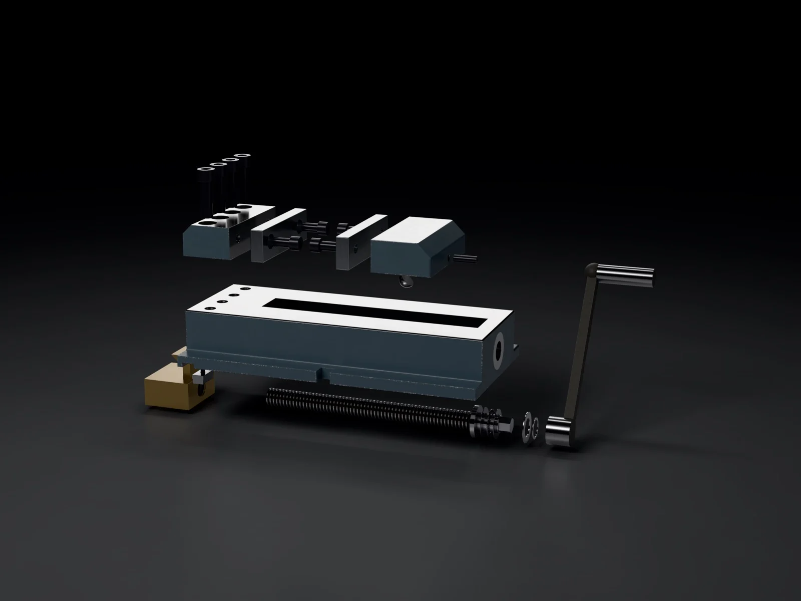
Make mounting points, connections and movement easier to review.
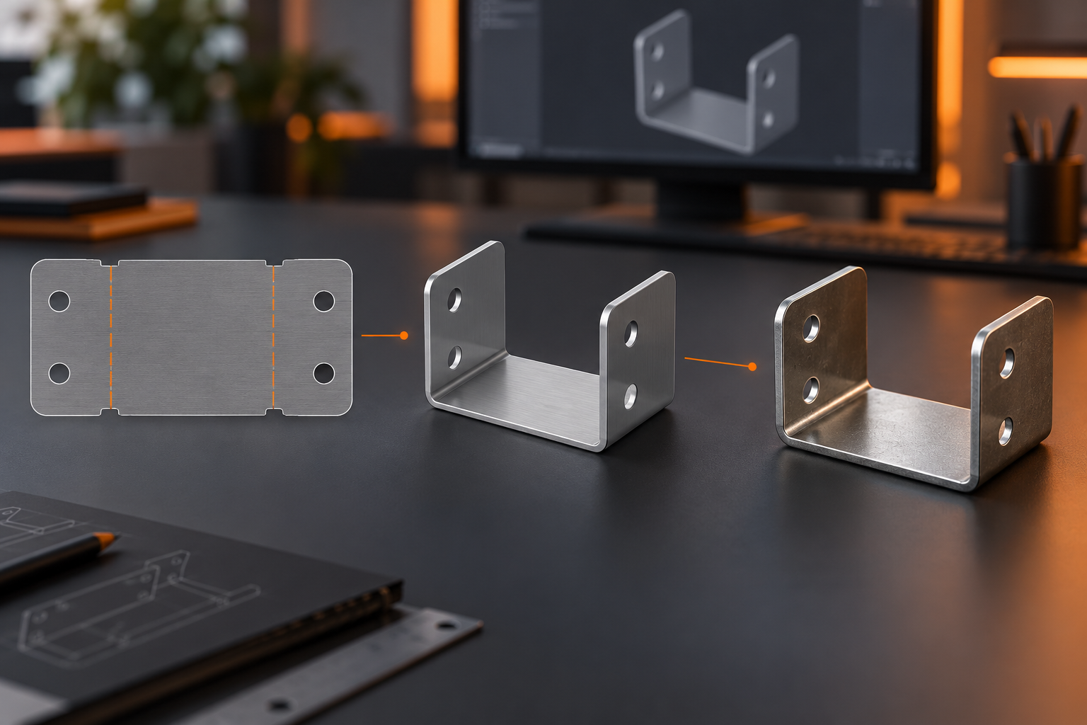
Explain a concept with renders or drawings for a review.
Your possible next step
What problem should it solve?
“I want a portable stand that holds my equipment at a comfortable height.”
Bring what you have. A rough sketch, a photo of the problem or just a description.
A concept helps choose a direction. It does not establish strength, safety or manufacturing readiness.
Your possible next step
Which details are known, and which need working out?
“I have the outline and two mounting measurements, but the thickness is still undecided.”
Bring what you have. Your sketch or drawing, any known units and the measurements you trust.
A model can match a sketch without being ready to manufacture. Missing details stay open for review.
Your possible next step
What connects, moves or must line up?
“This sensor needs to attach to an existing frame without blocking the adjustment knob.”
Bring what you have. Photos or models of the connecting parts and any trusted mounting measurements.
A visual assembly review is a starting point. Loads, fit limits and required checks must be agreed separately.
Your possible next step
Who needs to see it, and what decision should they make?
“I need a clear exploded view for a customer review, rather than a production drawing.”
Bring what you have. An existing model if you have one, reference images and where the visuals will be used.
A render explains appearance. A production drawing communicates different information; choose the deliverable for the job.
Visual examples show design possibilities, not promised deliverables. No material or manufacturing decisions are selected for you.
See the difference
You may need more than one kind of help. Pick one to understand what it does, then decide whether it belongs in your brief.
Choose a picture above to compare the type of help. Exploring does not change your brief.
What this helps with
Useful when you need to compare shapes, features or possible directions before committing to detail.
Useful starting information: Describe the problem, who will use it and any must-have features.
A concept is a discussion starting point. It does not confirm fit, strength or production readiness.
Starting with an idea ↗What this helps with
Useful when you need to develop dimensions, change geometry or review how parts connect.
Useful starting information: Bring known measurements with units, connecting parts and the details still undecided.
A CAD model describes geometry. Manufacturing requirements and any necessary engineering checks need their own review.
Preparing a CAD conversation ↗What this helps with
Useful for explaining appearance, an assembly sequence or a concept to customers and reviewers.
Useful starting information: Say who will see it, what you want them to understand and where the image will be used.
A polished image does not prove hidden geometry, real materials, performance or manufacturing readiness.
Choosing useful design information ↗What this helps with
Useful when a supplier needs views, dimensions and agreed requirements to discuss making or inspecting a part.
Useful starting information: Bring the latest model or drawing, critical connections and any supplier requirements you already know.
A drawing needs review for its intended use. Creating a drawing does not automatically release the design for production.
What a drawing handoff needs ↗Your starting point
Short answers are fine. “Not sure yet” is a useful answer too.
Supporting guides open in a separate tab so your answers stay here.
See an example of a useful design starting point ↗
Starting goal:
Select the text and copy it into your notes or a message. Nothing is sent from this page.
Review this draft and edit your answers above as needed. No choices have been approved or sent.
You review and send the email yourself. Nothing is sent automatically.
Have a specific technical question? The optional references below can help. You can leave these details for the design conversation.
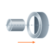
02 / Will these size limits overlap?
Enter the smallest and largest allowed sizes from your drawing. We’ll explain the possible diametral clearance, without choosing a fit class for you.
A dimensional overlap does not establish holding force, press capacity or safe assembly temperature.
What else does an interference fit need? →Positive means diametral clearance; negative means diametral interference. These size limits alone do not establish alignment, form, surface texture, coating allowance, assembly force, temperature behavior or performance.
Smallest clearance = smallest hole − largest shaft
Largest clearance = largest hole − smallest shaft
03 / Assembly questions
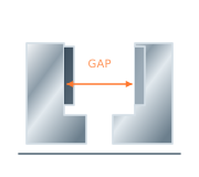
Add the dimensions that increase the gap and subtract those that reduce it. We’ll show the full range allowed by the limits you enter. This tool handles a one-dimensional chain with symmetric ± tolerances.
The nominal result is the signed sum of the dimensions. The worst-case ± variation is the sum of the absolute tolerances. Every included dimension can be at its allowed limit in the unfavorable direction. Statistical RSS can be useful with an appropriate process model, but this tool makes no probability or process-capability assumption.
This does not include angular effects, geometric tolerances, temperature, coating or deformation. Add the relevant requirements to your project review.
Read the assembly-gap guide → · Method reference: NIST tolerance analysis ↗
04 / Quantity questions
Compare how a one-time setup cost spreads across two quantities. Use figures from your supplier or your own planning assumptions; we do not supply a machine rate or quote.
The model assumes the same one-time setup and repeated cost at both quantities. It excludes anything you have not included: tooling, inspection, outside processing, tax, shipping, scrap or a second setup. A lower per-piece figure can still mean a larger total purchase.
Batch cost = setup + quantity × repeated per-part cost. Cost per piece = batch cost ÷ quantity. Ask your supplier which costs repeat per lot, which repeat per piece, and whether the process or price changes with quantity.
All outputs are planning calculations, not current ProtoChat service pricing or an accepted supplier quote.
05 / Operating conditions
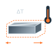
Explore free expansion using a mean coefficient for the temperature interval you are reviewing. This is a dimension question, not an interference-force or thermal-stress calculation.
The example uses Alleima’s Sanmac 304/304L metric mean value, 16.5 ×10⁻⁶/°C for 30–100 °C. A 100 mm reference dimension at 30 °C gives an estimated 0.1155 mm growth at 100 °C. It is not a generic coefficient for every stainless grade or temperature.
These are interval means, not instantaneous coefficients. A mean over a broad interval is not automatically the mean over a smaller interval within it. Use the named product and stated interval; no interpolation or automatic material selection.
| Temperature interval (°C) | Mean linear CTE (ppm/°C) |
|---|---|
| 30–100 | 16.5 |
| 30–200 | 17 |
| 30–300 | 17.5 |
| 30–400 | 18 |
| 30–500 | 18 |
| 30–600 | 18.5 |
| 30–700 | 18.5 |
Producer source: physical properties / thermal expansion ↗
Change = reference dimension × mean CTE ×10⁻⁶ × (final temperature − initial temperature). Final dimension = reference dimension + change. Assumes an applicable constant mean coefficient and free, uniform expansion along the chosen direction. Restraint, gradients, anisotropy, phase changes and temperature-dependent coefficients need another model. The result does not predict whether an assembly will work.
06 / Finishing questions
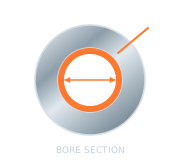
Compare diameter limits before and after a uniform additive buildup. Use the finishing supplier’s outward buildup beyond the original surface, not a generic coating thickness.
If you only know total film thickness, ask your finisher for growth, penetration and any pretreatment removal. Anodizing is not a universal “add the full coating thickness” process. No default growth factor is supplied here.
Bore: smallest final = smallest initial −2×maximum buildup; largest final = largest initial −2×minimum buildup. For an outside diameter, add twice the buildup using matching lower and upper bounds. Buildup in µm is divided by 1,000 to use mm. Assumes a uniform additive layer on both opposing surfaces; excludes pretreatment material removal, masking, threads, form error and uneven deposits.
Read the finish and coating guide → · Finisher reference: buildup versus penetration ↗
07 / Reading a drawing
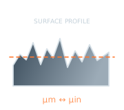
Ra, Rq and Rz describe different surface characteristics. This tool changes µm ↔ µin within your selected parameter; it does not estimate one parameter from another.
1 µin =0.0254 µm exactly. The displayed result is rounded. Keep the drawing’s governing standard, filtering, evaluation conditions and acceptance rule; conversion does not change them.
NIST unit-conversion reference ↗ · Mitutoyo roughness-parameter reference ↗
08 / Threaded-hole questions
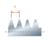
A thread name, usable thread depth and fastener engagement answer different questions. Record what you know and keep the rest open for review.
This saves a text file on your device. It does not upload, submit a project or save to an account.
These twelve entries match the supplier’s pitch chart. Other fine pitches and thread systems exist. Nominal major diameter is a designation, not a measured size limit.
| Designation | Nominal major (mm) | Pitch (mm) | Listed series |
|---|---|---|---|
| M3 × 0.5 | 3 | 0.5 | coarse |
| M3 × 0.35 | 3 | 0.35 | fine reference |
| M4 × 0.7 | 4 | 0.7 | coarse |
| M4 × 0.5 | 4 | 0.5 | fine reference |
| M5 × 0.8 | 5 | 0.8 | coarse |
| M5 × 0.5 | 5 | 0.5 | fine reference |
| M6 × 1 | 6 | 1 | coarse |
| M6 × 0.75 | 6 | 0.75 | fine reference |
| M8 × 1.25 | 8 | 1.25 | coarse |
| M8 × 1 | 8 | 1 | fine reference |
| M10 × 1.5 | 10 | 1.5 | coarse |
| M10 × 1.25 | 10 | 1.25 | fine reference |
Checked 2026-10-24. norelem source: thread pitch chart ↗
Read the holes and blind-thread guide → · Prepare the mating-component requirements →
Before you share files
Do not upload files here. Arrange the appropriate transfer route before sharing controlled technical data.
Read the CAD handoff guide → · Review the drawing checklist →
For a part already headed toward machining, compare a starting blank separately.
Plan a machining blank →