The starting question
Usable thread depth is not drill depth.

See the difference
Drilled hole: define the endpoint
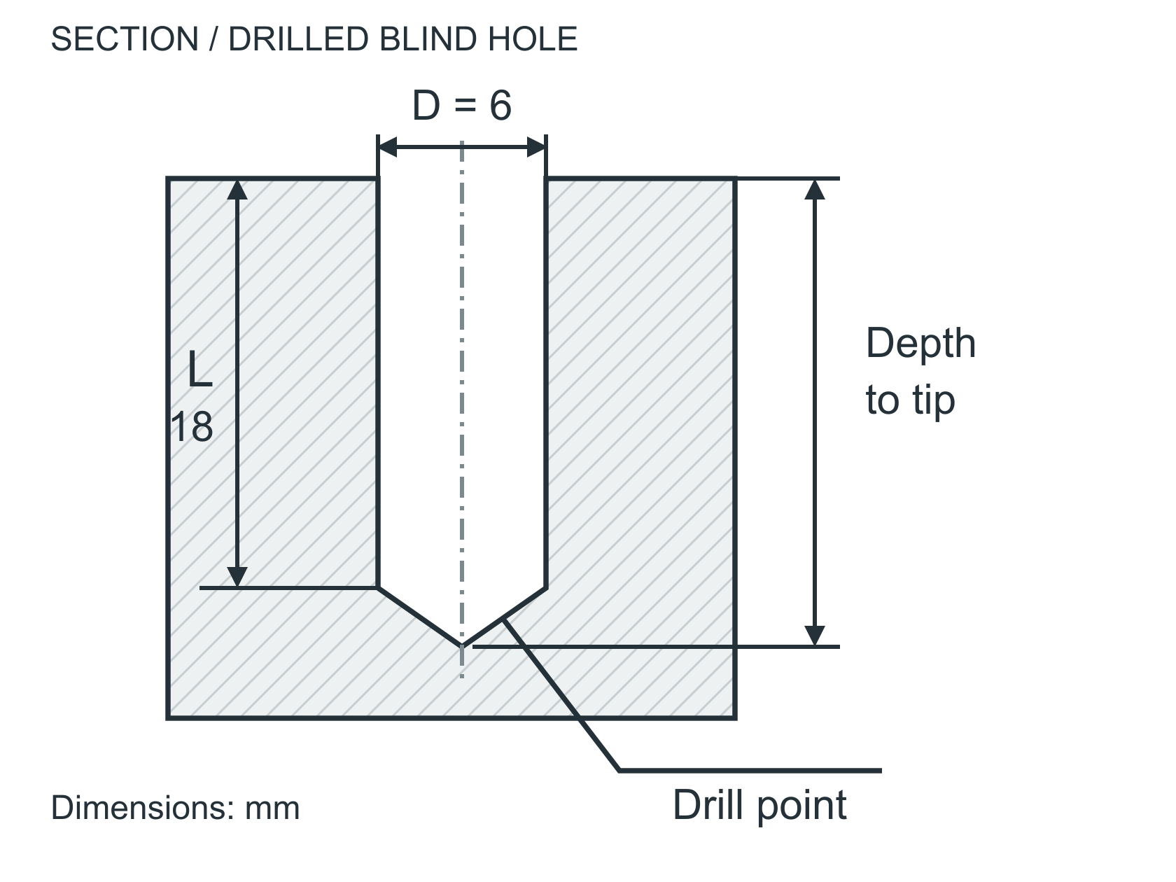
A depth to the tip includes the conical bottom. It is not the same as full-diameter depth.
Blind thread: reserve bottom space
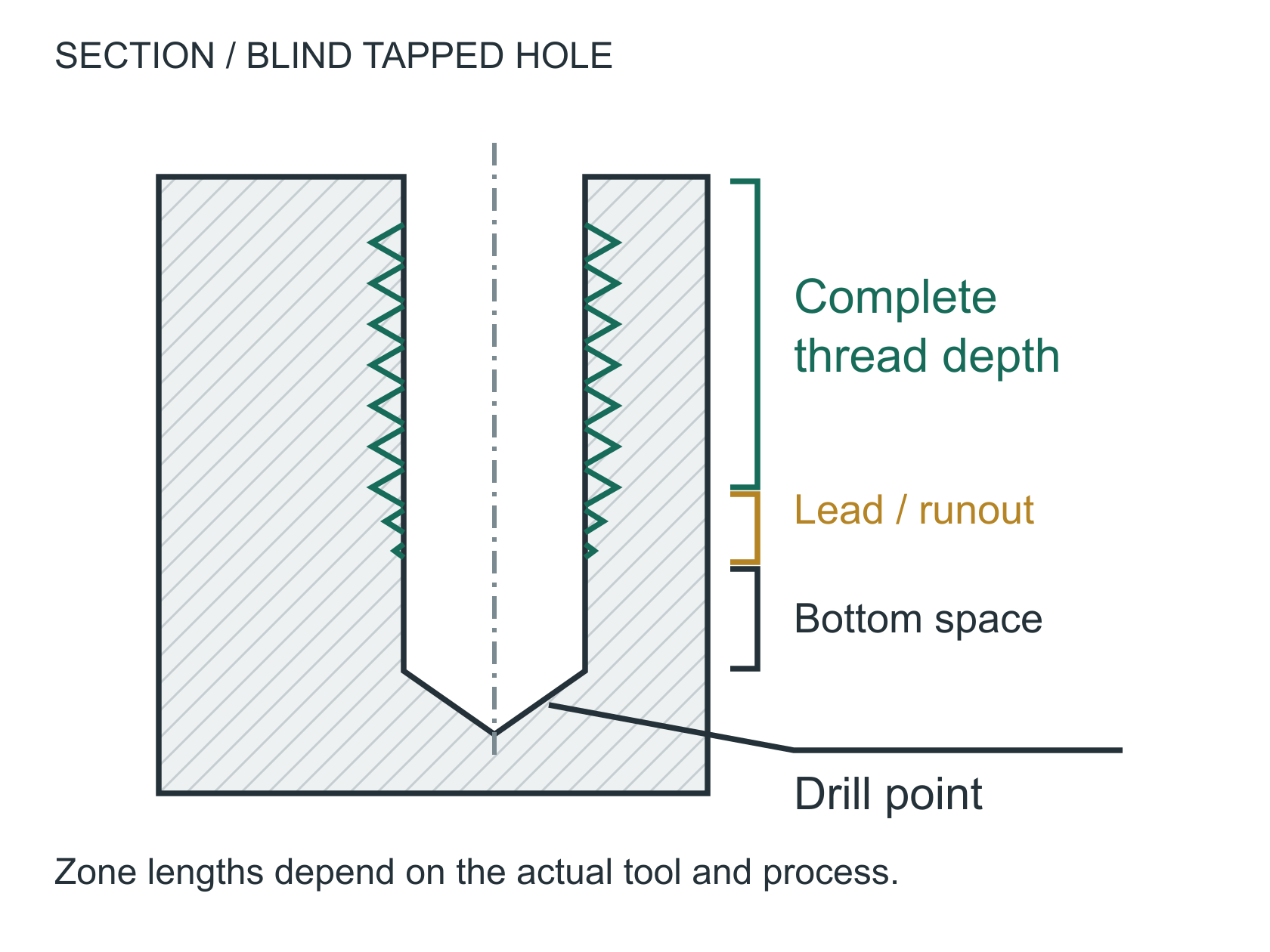
Bolt engagement is the actual overlap of mating threads. It is not set by drill depth alone.
Hole ratio = full-diameter depth / bore diameter
18 / 6 = 3:1 | 60 / 6 = 10:1Left: a 6 mm bore with 18 mm full-diameter depth has L/D = 3. A 60 mm depth at the same diameter would be 10. Right: blind-thread zones are schematic, with no universal bottom-clearance dimension.
Specify complete usable thread depth. Set lead, runout and bottom allowance using the selected tool and chip strategy.
For your own project
Which part do you need help with?
Start with what you know. Keep the undecided details open for discussion.
You bring
Your sketch, drawing or existing CAD, including known units.
We can help explore
Clearer geometry and the details still missing from the design.
Discuss next
Which dimensions are trusted, and which need review?
Start with the connection you need designed
Tell ProtoChat which parts must connect and what you need to decide: hole location, a mating component, assembly access or a drawing for review. Bring the model, sketch or supplier requirement you already have, and keep undecided details open.
Ask for the digital deliverables that help your next step. A customer choice records design intent; it does not by itself establish thread strength or manufacturing acceptance.
Explore drilling tools at Sandvik Coromant ↗. Manufacturer reference; unpaid link. Explore the tooling categories with the responsible supplier; no drill, pre-hole diameter or process is selected here.
Depth callouts
State whether hole depth is to the drill tip or to full diameter. For blind threads, specify complete usable thread depth, not an ambiguous tap depth.
Thread clearance
Keep bolt engagement, complete thread depth, tap lead/runout and drill-point allowance separate. Select bottom clearance from the actual tool and chip strategy, not a fixed extra multiple of diameter.
Process selection
Deep holes require coolant, chip and guidance planning. Select the drilling process from the actual depth, diameter, material and tooling; a depth ratio alone does not mandate gun drilling.
Select cut or form tapping with the tool supplier for the actual alloy and condition. Form taps displace material and need the specified pre-hole size. A cut-tap drill table is not a form-tap table.
Bring this to the review
Your working checklist
Use these prompts to record open questions. Checking a box does not approve a design or manufacturing process. Selections last for this page visit.
References & further reading
- norelem — thread pitch chart, nominal size/pitch subset only ↗
- OSG — a specific forming-tap application example, not a universal drill chart ↗
References support the named topic; they do not certify a design, setup or product.
Planning guidance and illustrative examples. Confirm project-specific requirements with the responsible design, manufacturing and quality teams.
No paid placement or affiliate links in this guide.