The starting question
Which dimensions must the formed part meet, and which bend rule will the fabricator actually use?
For your own project
Which part do you need help with?
Start with what you know. Keep the undecided details open for discussion.
You bring
An idea, a rough sketch or an example of the problem.
We can help explore
Possible shapes, features and a clearer concept to discuss.
Discuss next
What must it do, and which questions matter most?
Describe the design help you need
Are you starting with an idea, revising an enclosure or bracket, or preparing a model for a fabrication discussion? Tell ProtoChat which shape, connection or assembly question needs to be resolved.
Bring the sketch or model you have and identify the required digital deliverables. Keep numerical thickness and other undecided requirements open for review rather than choosing a generic value to complete the brief.
Specify the formed requirement
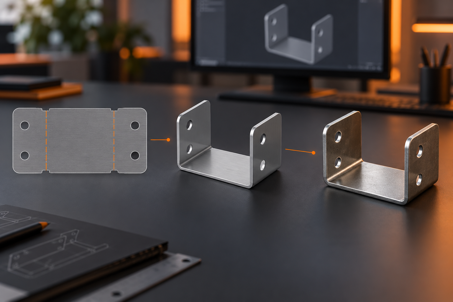
Record the material grade and condition, numerical thickness with units, inside bend radius and required finished dimensions. Label the angle convention: an included angle and a rotation from flat are different descriptions, even when a right-angle example hides the difference.
Mark where each flange dimension starts and ends. A tangent point, theoretical outside intersection and physical edge are different references. Give the fabricator the formed requirement and identify which flat-pattern file or bend-rule revision accompanies it.
Treat K-factor as a named input
Autodesk defines K-factor as the neutral-axis offset from the inner bend surface divided by sheet thickness. In an invented geometry example, a 0.8 mm offset divided by 2 mm thickness gives K =0.4. That calculation explains the ratio; it does not recommend K =0.4 for a material or tool.
Fusion stores thickness, bend radius and unfold settings in a sheet-metal rule. Record the applicable rule and its source rather than assuming a material label alone establishes a production flat pattern.
Keep unverified defaults out of the purchase
Use numerical thickness with units, and ask your fabricator to confirm the forming data for the actual material and tooling.
Before releasing a blank for cutting, ask who owns the flat pattern, which revision is current, and how the formed dimensions will be checked. Leave missing bend information as an open question instead of silently substituting a generic preset. This guide does not select tooling, predict springback or certify bendability.
Explore press-brake tooling at Wilson Tool ↗. Manufacturer reference; unpaid link. Review tooling context with the intended fabricator; this link does not establish compatibility, capacity or a bend rule for your part.
Bring this to the review
Your working checklist
Use these prompts to record open questions. Checking a box does not approve a design or manufacturing process. Selections last for this page visit.
References & further reading
References support the named topic; they do not certify a design, setup or product.
Planning guidance and illustrative examples. Confirm project-specific requirements with the responsible design, manufacturing and quality teams.
No paid placement or affiliate links in this guide.