The starting question
The cutter must fit the corner AND reach the floor.
See the difference
Equal radii: no sweep radius
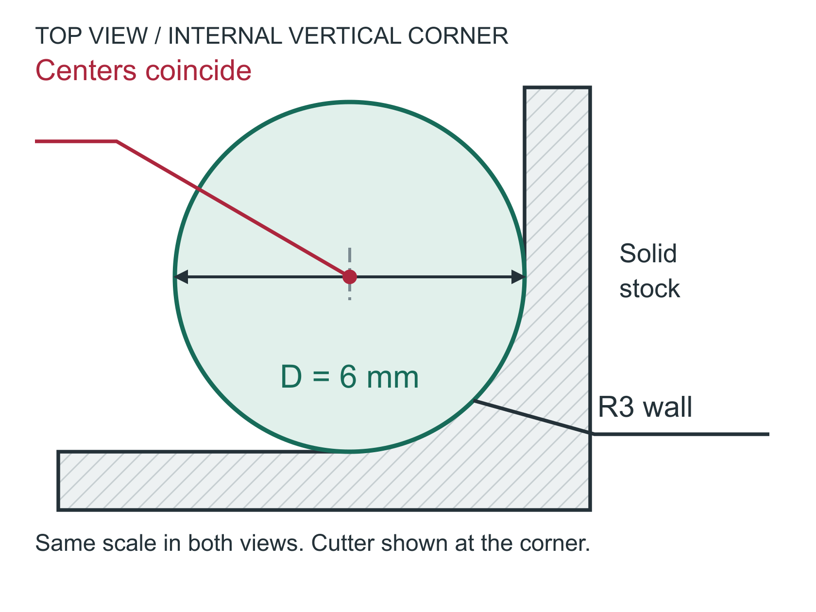
The cutter-center path turns at a point. Increasing pocket depth does not change this corner fit.
Larger corner: room to sweep
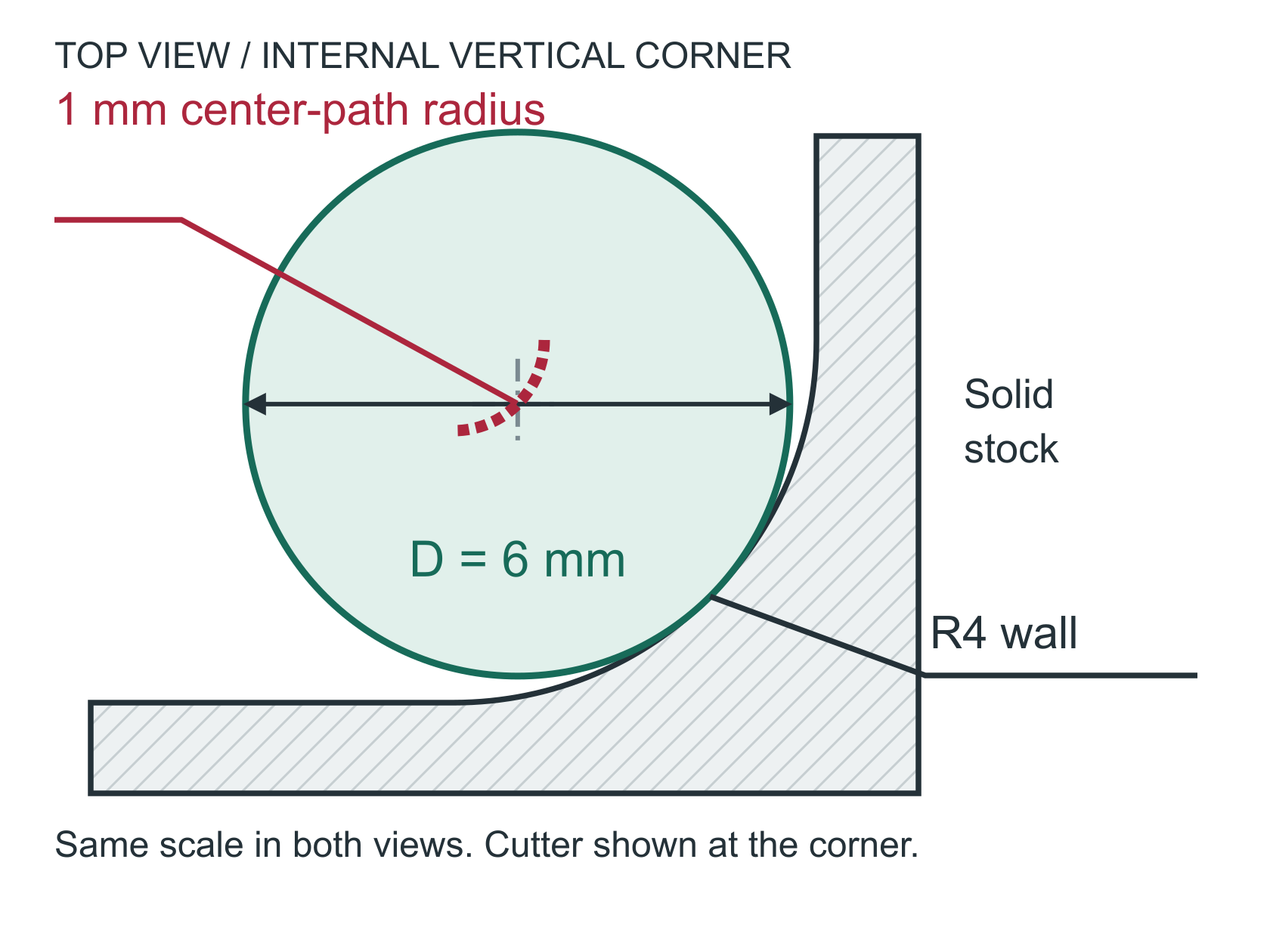
The center can follow a 1 mm-radius arc. The cutting edge still contacts the finished wall.
Cutter-center path radius = R - D/2 (for R ≥ D/2)
R3: 3 - 6/2 = 0 mm | R4: 4 - 6/2 = 1 mmBoth examples assume 24 mm pocket depth, which is not shown in these top views. For a 6 mm cutter, an R3 corner gives a zero cutter-center turn radius; R4 gives a 1 mm center-path radius. Depth / cutter diameter remains 4:1. These are geometric relationships, not tool reach or machining approval.
A larger corner helps the toolpath; it does not prove tool reach. Check flute, neck and holder clearance separately.
For your own project
Which part do you need help with?
Start with what you know. Keep the undecided details open for discussion.
You bring
Your sketch, drawing or existing CAD, including known units.
We can help explore
Clearer geometry and the details still missing from the design.
Discuss next
Which dimensions are trusted, and which need review?
Corner clearance
A larger internal vertical radius gives the cutter room to sweep through the corner. Verify the mating part before changing it; a functional sharp corner may need relief or another process.
Reach is not just depth
Check flute length, relieved neck, holder diameter and adjacent walls. A cutter can reach the floor while its holder still collides with the part.
Process boundary
Wire EDM needs an accessible through-cut in conductive material. A blind pocket requires a different approach; do not specify wire EDM simply because a corner is square.
In any alloy, long tools and unsupported walls need joint review. Hardness, tool geometry and cutting conditions change the workable envelope; no universal L/D ratio establishes capability.
Bring this to the review
Your working checklist
Use these prompts to record open questions. Checking a box does not approve a design or manufacturing process. Selections last for this page visit.
Planning guidance and illustrative examples. Confirm project-specific requirements with the responsible design, manufacturing and quality teams.
No paid placement or affiliate links in this guide.